We have compiled a list of manufacturers, distributors, product information, reference prices, and rankings for 3D CAD.
ipros is IPROS GMS ・ IPROS One of the largest technical database sites in Japan that collects information on.

3D CAD(図面) - List of Manufacturers, Suppliers, Companies and Products | IPROS GMS

Last Updated: Aggregation Period:Sep 16, 2026~Oct 13, 2026
This ranking is based on the number of page views on our site.

3D CAD Product List

1~30 item / All 40 items

Displayed results

BIM Software [Revit] User Case Vol. 5

Significant automation of construction drawing creation using BIM!

We would like to introduce a case study of how Hi-Big Architectural Drawing Studio utilized Autodesk's BIM software "Revit." <Overview> When creating drawings from a BIM model, manually inputting dimension lines and tags that represent the specifications of components can lead to significant effort in the creation of drawings and design changes. Hi-Big Architectural Drawing Studio successfully automated the drawing creation process significantly by utilizing the BIM software "Revit." <Implementation Results> Please check the PDF materials for more details.

  • 3D CAD
  • 2D CAD Construction
  • Other CAD related software
  • 3D CAD

Added to bookmarks

Bookmarks list

Bookmark has been removed

Bookmarks list

You can't add any more bookmarks

By registering as a member, you can increase the number of bookmarks you can save and organize them with labels.

Free membership registration

Until when will we differentiate between 2D CAD and 3D CAD?

Eliminate hassle with the linkage between drawings and models 'CADPAC'

Are you currently using both 2D CAD and 3D CAD and experiencing any of these frustrations? - Going back and forth between 2D CAD and 3D CAD - There's no time on-site, so only the drawings are modified. The drawings are left to stand alone. - You went through the trouble of implementing 3D CAD, but... - You've ended up going back to 2D CAD. With CADPAC3D, models and drawings are linked in real-time. When the model is created, the drawing is also created! ■ CAD Usability What designers need is the realization of their ideas. There's no time to be tossed around by CAD. With intuitive operations, learning is a breeze. You no longer need unwanted breaks. With CADPAC, even modification tasks respond immediately. This could be the opportunity to change your common sense.

  • nws_05.png
  • 3D CAD
  • 2D CAD machine
  • Other CAD
  • 3D CAD

Added to bookmarks

Bookmarks list

Bookmark has been removed

Bookmarks list

You can't add any more bookmarks

By registering as a member, you can increase the number of bookmarks you can save and organize them with labels.

Free membership registration

3D CAD "KEYCREATOR"

Fusion of 3D functionality and 2D drawing capabilities! Comprehensive support for the design trial and error process.

"KEYCREATOR" is a system that allows anyone to easily create 3D models with the feeling of drawing three-view drawings in 2D design. By avoiding careless mistakes during 2D design, it achieves a reduction in design time. By effectively utilizing existing 2D data, it eliminates the hassle of re-entering shapes while referring to 2D drawings, and thanks to interfaces with various 3D CAD systems, smooth work can be done without the need for intermediate file data compatibility. [Features] ■ Direct editing is possible even with data converted from other CAD systems. ■ 2D drawings, 3D wires, surfaces, and solids can all be used together in the same space. ■ Direct shape changes can be made simply by changing the dimension numbers. *For more details, please refer to the PDF materials or feel free to contact us.

Added to bookmarks

Bookmarks list

Bookmark has been removed

Bookmarks list

You can't add any more bookmarks

By registering as a member, you can increase the number of bookmarks you can save and organize them with labels.

Free membership registration

BIM compatible. Free 3D CAD seminar for the construction, equipment, and plant industries.

We introduced 3D CAD for efficiency, but the workload keeps increasing... Many companies share the same concern. Shall we unravel this contradiction?

Are you facing problems like these? - I introduced 2D CAD because I couldn't create drawings with 3D CAD. - Every time I modify the 3D data, I have to update the drawings, which is a hassle. I can't keep up with the revisions. - There are many missed or incorrect modifications in the drawings, so I'm managing to get by with 'on-site adjustments.' The BIM-compatible 3D CAD system 'TopSolid’Design7' that we will introduce in this seminar solves the issues faced by the construction, equipment, and plant industries. - It can handle the entire workflow from planning and design to the creation of construction drawings within a single system. - The 3D data and 2D drawings are linked, so when there are design changes, you only need to modify the 3D data, and all drawings will be automatically updated, eliminating mistakes and omissions, significantly improving productivity. - It is compatible with BIM, the industry-standard format, allowing you to share 3D data with partner companies.

Added to bookmarks

Bookmarks list

Bookmark has been removed

Bookmarks list

You can't add any more bookmarks

By registering as a member, you can increase the number of bookmarks you can save and organize them with labels.

Free membership registration

Industrial Design 3D CAD ThinkDesign Styling

3D CAD suitable for industrial design through 3D modeling.

"Think Design Styling" is the ideal 3D modeling tool for industrial design work involving products with complex freeform surfaces. It supports surface features including GSM with highlight control, high-quality still image rendering, and drawing creation.

  • 3D CAD
  • Rendering software
  • Other CAD
  • 3D CAD

Added to bookmarks

Bookmarks list

Bookmark has been removed

Bookmarks list

You can't add any more bookmarks

By registering as a member, you can increase the number of bookmarks you can save and organize them with labels.

Free membership registration

SOLIDWORKS Basic Operation Training (On-site)

Training service to master the basic operations of SOLIDWORKS.

This is a curriculum consisting of four sessions, each lasting six hours, aimed at mastering a series of basic operations related to parts, assemblies, and drawings, in accordance with the text.

  • 3D CAD
  • 3D CAD

Added to bookmarks

Bookmarks list

Bookmark has been removed

Bookmarks list

You can't add any more bookmarks

By registering as a member, you can increase the number of bookmarks you can save and organize them with labels.

Free membership registration

[Tekla Structures Domestic Case Study] Takenaka Corporation

A case study utilizing Tekla Structures was published in the "Daily Construction Communication News."

In the November 29, 2024 issue of the "Daily Construction Communication Newspaper," a case study from our client was featured. "First in Japan to Apply 'Approval Within BIM Model'" The major general contractor, Takenaka Corporation, has completely eliminated traditional 2D detailed drawings and was the first in Japan to apply "Approval Within BIM Model." "We accomplished everything with the Tekla model instead of creating detailed drawings. The approval process has been shortened for both the general contractor and the steel fabricator due to the approval within the model, leading to a reduction in the creation of detailed drawings," they discussed the effects. For more details on this initiative that overturns the conventional wisdom of "not relying on drawings," please check out the article.

Added to bookmarks

Bookmarks list

Bookmark has been removed

Bookmarks list

You can't add any more bookmarks

By registering as a member, you can increase the number of bookmarks you can save and organize them with labels.

Free membership registration

[BIM Software Implementation Case Study] Metropolitan Bus Terminal

All 3D models, including documents such as production drawings and work processes, are created using Tekla Structures!

The Integrated Transport Center is the largest investment project of the Lublin city government, and as part of this, the contractor Budimex has constructed a new bus station along with the reconstruction of the transport system. The company responsible for this impressive steel structure is Mostostal Kraków. The highlight of this project, the Lublin Metropolitan Bus Terminal's roof, is a representative landmark of Lublin, with the weight of the steel columns and truss sections with crowns totaling approximately 1550 tons. Its artistic appearance is composed of precise processing techniques and complex welding. MTA Engineering was responsible for the structural calculations, and the design engineering department of Mostostal Kraków led the detailed design work. The station's roof was designed as a spatial structure, supported by diagonal columns. All 3D models, including production drawings and work process documents, were created using Tekla Structures.

  • 3D CAD
  • 2D CAD Construction
  • antenna
  • 3D CAD

Added to bookmarks

Bookmarks list

Bookmark has been removed

Bookmarks list

You can't add any more bookmarks

By registering as a member, you can increase the number of bookmarks you can save and organize them with labels.

Free membership registration

[Domestic Utilization Case Studies] Steel Frame Detailed Modeling

A case study utilizing Tekla Structures for steel detailing modeling has been published in the "Nikkankensetsu Tsushin Shimbun."

By downloading the PDF, you can view the catalog for the structural BIM software 'Tekla Structures' (Steel Detail Modeling) and case study articles on its use in Japan. (If the PDF button is not displayed) ⇩ Case study articles can be downloaded from the special site below ⇩

  • 3D CAD
  • antenna
  • 2D CAD Construction
  • 3D CAD

Added to bookmarks

Bookmarks list

Bookmark has been removed

Bookmarks list

You can't add any more bookmarks

By registering as a member, you can increase the number of bookmarks you can save and organize them with labels.

Free membership registration

BIM modeling construction/creation service

We don't have enough manpower for building/creating BIM models! There's no time to learn from now on! Our company, with abundant experience and achievements, will solve such concerns!

Our company provides high-quality BIM Integration Services to our clients, leveraging our practical experience on construction sites, years of utilizing BIM software, and a proven track record in building BIM models across various fields. We specialize particularly in creating BIM models from 2D drawings and offering Revit family creation services, especially during the initial phase of BIM application. This part of the process can be labor-intensive but is well-suited for outsourcing due to its manageable nature. Additionally, we will respond to CIM applications through our experienced Alliance Partners. Please feel free to contact us if you have any requests. 【Features】 ■ Extensive BIM modeling experience at our headquarters in Taiwan ■ Rich experience in BIM specialization from field-experienced professionals ■ Efficient and effective BIM project management ■ Diverse smart solutions for the construction industry ■ Fast and high-precision Revit family creation *For more details, please download the PDF or feel free to contact us.

  • 3D CAD
  • Other office supplies
  • Virtual Reality Related
  • 3D CAD

Added to bookmarks

Bookmarks list

Bookmark has been removed

Bookmarks list

You can't add any more bookmarks

By registering as a member, you can increase the number of bookmarks you can save and organize them with labels.

Free membership registration

Proposal for the Utilization of CAD: BIM

Compatible with IFC4.0! It is possible to utilize DWG data directly for 3D data and BIM.

In the architecture and civil engineering industry, there are various challenges faced when adopting BIM. Challenges related to the design process, infrastructure, and costs are noted, and 'BricsCAD' is capable of addressing these issues. The BIM option of this product is low-cost compared to typical BIM software, making it affordable for companies supporting the field. It can accommodate BIM modeling. 【Reasons and Benefits of Introducing BIM】 ■ Design documents can be consolidated into a single model. ■ Consistency across drawings is maintained, and design changes can be reflected in all related drawings. ■ High-accuracy feasibility studies can be conducted from the planning stage. *For more details, please refer to the related links or feel free to contact us.

Added to bookmarks

Bookmarks list

Bookmark has been removed

Bookmarks list

You can't add any more bookmarks

By registering as a member, you can increase the number of bookmarks you can save and organize them with labels.

Free membership registration

[BIM Software Implementation Case Study] Transformation of North Sea Oil Field Platform Construction

Efficient design and manufacturing automation! Achieving advanced automation in the design and manufacturing processes!

The two platforms of the Johan Sverdrup oil field are designed and manufactured by the Norwegian company Aibel. Currently, the company's massive project is transitioning from a shipyard in the tropical region of Thailand to the rough seas of the North Sea. This project faced challenges such as compliance with standard requirements in the oil and gas industry and the integration of Tekla software with existing solutions. To address these challenges, experts in three-dimensional design using Tekla software collaborated to successfully semi-automate the drawing creation process with Tekla. They generated accurate information in a data format suitable for collaboration with machine tools, achieving up to 95% efficiency in the company's production labor and quality. *For more details, please refer to the PDF materials or feel free to contact us. (If the PDF button is not displayed) ⇩ The catalog can be downloaded from the special website below ⇩

  • 3D CAD
  • antenna
  • 2D CAD Construction
  • 3D CAD

Added to bookmarks

Bookmarks list

Bookmark has been removed

Bookmarks list

You can't add any more bookmarks

By registering as a member, you can increase the number of bookmarks you can save and organize them with labels.

Free membership registration

[BIM Software Implementation Case Study] Karasuma Racecourse Redevelopment Project

Tekla is effective for designing buildings with large curves! Examples from redevelopment projects such as spectator stands.

The redevelopment of the Karasuyama Racecourse is a project to construct world-class facilities. The company responsible for the project is handling everything from design to detailed design, manufacturing, and the construction of the main viewing stand roof using a 45-meter cantilever beam. The very complex roof shape had significant restrictions on deflection and allowable tolerances, but by utilizing "BIM" and "Tekla Structures," they conducted precise detailed design that considered the use of fabrication drawings. [Case Overview] ■ Challenge: The very complex roof shape had significant restrictions on deflection and allowable tolerances. ■ Results - Achieved precise detailed design that considered the use of fabrication drawings. - Tekla is very effective for designing buildings with large curves, like the Karasuyama Racecourse. *For more details, please refer to the PDF materials or feel free to contact us. (If the PDF button is not displayed) ⇩ The catalog can be downloaded from the special website below ⇩

  • 2D CAD Construction
  • 3D CAD
  • Modeler
  • 3D CAD

Added to bookmarks

Bookmarks list

Bookmark has been removed

Bookmarks list

You can't add any more bookmarks

By registering as a member, you can increase the number of bookmarks you can save and organize them with labels.

Free membership registration

Fusion 360 - Cloud-based 3D CAD -

A cloud-based product development platform for 3D CAD/CAM/CAE.

Fusion 360 is software that consolidates all the necessary functions for various manufacturing environments into one platform. It is equipped with 3D modeling, assembly, 2D drawing creation, analysis functions, and CAM (Computer-Aided Manufacturing) capabilities for creating cutting tool paths, as well as features for higher-quality product design, such as circuit design and generative design tools that utilize AI. Additionally, by leveraging cloud technology, it enables reduced analysis computation times and data sharing that is not limited by location.

  • 2D CAD machine
  • 3D CAD
  • 3D CAD

Added to bookmarks

Bookmarks list

Bookmark has been removed

Bookmarks list

You can't add any more bookmarks

By registering as a member, you can increase the number of bookmarks you can save and organize them with labels.

Free membership registration

3D CAD ZW3D Professional

Mold design functionality, point cloud necessary for reverse engineering, importing STL, surface creation, equipped with part library.

ZW3D Professional is designed for mold design and reverse engineering. In addition to standard features, it includes modules necessary for mold design, such as slope analysis, cavity-core splitting, parting lines & surfaces, and electrode design. It also encompasses point cloud and STL import, as well as surface creation needed for reverse engineering, allowing for the scanning of handmade models and old molds to replicate them as digital data.

  • 3D CAD
  • Data conversion software
  • Modeler
  • 3D CAD

Added to bookmarks

Bookmarks list

Bookmark has been removed

Bookmarks list

You can't add any more bookmarks

By registering as a member, you can increase the number of bookmarks you can save and organize them with labels.

Free membership registration

[BIM Software Implementation Case Study] Forum Groningen

The created drawings total over 28,000 sheets! Temporary support structures used during installation have also been modeled!

The steel structure of the Forum Groningen, designed by NL Architects, consists of eight steel "masses" made of spatial trusses fixed on two concrete cores that serve as the foundation. These concrete cores are connected at the top by a bridge structure, designed to have deflections in separate directions, requiring the steel "masses" to also face in their respective directions. The detailed design, fabrication, assembly, tolerance assurance, and logistics of such a twisted structure proved to be complex, presenting significant challenges. As a result, all of the main structure, as well as the supporting structure of the facade made of natural stone that moves in three directions (2,600 tons), were modeled using Tekla. The design, modeling, production drawing creation, fabrication, and installation were carried out concurrently at two locations, but were executed on schedule thanks to the collaboration of the engineering team. *For more details, please refer to the PDF materials or feel free to contact us. (If the PDF button is not displayed) ⇩ The catalog can be downloaded from the special site below ⇩

Added to bookmarks

Bookmarks list

Bookmark has been removed

Bookmarks list

You can't add any more bookmarks

By registering as a member, you can increase the number of bookmarks you can save and organize them with labels.

Free membership registration

[BIM Software Implementation Case Study] Brookfield Place Tower

Widely used for identifying interference points with design! We will introduce case studies of BIM software implementation.

The ICD Brookfield Place Tower, with 54 floors and a height of 282 meters, was constructed at the Dubai International Financial Centre. Considering the complex shape and the precision required at each construction stage, the steel structure design using Tekla played a crucial role in the project's success. "Tekla BIMsight" was widely used to identify interference points in the design by contractors for the roof and facade, equipment vendors, concrete contractors, and other stakeholders, and the detected interference points were resolved during the design phase. Adjusting the unique and complex steel structure was a challenging task, but BIM facilitated smooth coordination with the design and other stakeholders, as well as the generation of fabrication drawings, contributing to successful construction on schedule. *For more details, please refer to the PDF materials or feel free to contact us. (If the PDF button is not displayed) ⇩ The catalog can be downloaded from the special site below ⇩

  • Software (middle, driver, security, etc.)
  • Other CAD related software
  • 3D CAD

Added to bookmarks

Bookmarks list

Bookmark has been removed

Bookmarks list

You can't add any more bookmarks

By registering as a member, you can increase the number of bookmarks you can save and organize them with labels.

Free membership registration

Productivity of Steel Frame Fabrication Evolving with BIM: Structural BIM Software

◆ Improvement of productivity, integration with automatic processing machines and assembly robots for steel frame production ◆ 3D software 'Tekla Structures'

"Tekla Structures" is a BIM software for structural detailing. By utilizing the detailed and accurate 3D models of Tekla Structures, which are modeled to a construction-ready level, unexpected costs and rework can be minimized, optimizing the entire process and enabling the realization of more profitable projects. The BIM models of Tekla software facilitate collaboration in design, fabrication, and site management, improving workflows not only in the office but also on construction sites. [Other Features] - Integrated management of all structural information from basic design to detailed design, estimation, production management, and construction on a 3D model, regardless of material or structural type. - Automatic generation of drawings, reports, and NC data from the model, allowing for reduced design time, quick and flexible responses to design changes, and the elimination of drawing inconsistencies. - Excellent operability with a GUI and graphic processing that comply with Windows standards, enabling the rapid generation of 3D models. (If the PDF button is not displayed) ⇩ The catalog can be downloaded from the special website below ⇩

Added to bookmarks

Bookmarks list

Bookmark has been removed

Bookmarks list

You can't add any more bookmarks

By registering as a member, you can increase the number of bookmarks you can save and organize them with labels.

Free membership registration

Precast BIM Software Tekla Structures

Structural BIM software 'Tekla Structures' achieves productivity improvement and cost reduction through detailed structural calculations.

"Tekla Structures" allows for the construction of 3D models of precast concrete structures and enables the management of various information related to manufacturing and construction on a BIM model. By creating 3D models of concrete and rebar components, it can be utilized from basic design to structural calculations, detailed design, site construction, and management, achieving improvements in productivity and cost reduction. In the 3D model, it is possible to check in advance the intersections between rebars, the interference between rebars and steel frames, and the interference with equipment, thereby eliminating issues on site. The placement, joints, and anchoring of rebars can be automatically generated simply by specifying the parameters of the provided components, allowing for accurate tracking of material quantities. From the model, necessary drawings and documentation for manufacturing and construction, such as axis diagrams, rebar detail drawings, and rebar processing drawings, are automatically generated, enabling quick responses to design changes and avoiding inconsistencies between design information and manufacturing drawings. (If the PDF button is not displayed) ⇩ The catalog can be downloaded from the special site below ⇩

  • 3D CAD
  • 2D CAD Construction
  • antenna
  • 3D CAD

Added to bookmarks

Bookmarks list

Bookmark has been removed

Bookmarks list

You can't add any more bookmarks

By registering as a member, you can increase the number of bookmarks you can save and organize them with labels.

Free membership registration

BIM Software [Revit] User Case Vol. 1

The opening of the "ROOFLAG Rental Housing Future Exhibition Hall," a wooden large-roofed building that is one of the largest in the country, has been realized through the utilization of BIM.

We would like to introduce a case study where Daito Trust Construction Co., Ltd. utilized Autodesk's BIM software "Revit." <Overview> Daito Trust Construction opened the "ROOFLAG Rental Housing Future Exhibition Hall," a facility aimed at considering the future of rental housing. This was their first experience using large CLT panels as beams, and the project progressed in a trial-and-error manner without knowing where the challenges lay. <Issues and Reasons for Implementation> - It was difficult to consider the construction procedures and quality assurance of the large roof using only 2D drawing information. - They wanted to utilize a BIM model to understand the entire building. <Implementation Results> Please check the PDF document for details!

  • 3D CAD
  • 2D CAD Construction
  • 3D CAD

Added to bookmarks

Bookmarks list

Bookmark has been removed

Bookmarks list

You can't add any more bookmarks

By registering as a member, you can increase the number of bookmarks you can save and organize them with labels.

Free membership registration

Nine Criteria for Selecting a 3D CAD System [Basic Knowledge]

By using an appropriate 3D CAD system, it is possible to lead the project to success and lay the foundation for future growth and innovation.

Whether you are a CAD beginner or an experienced designer, it is essential to choose the right 3D CAD system for the success and efficiency of your project. CAD solutions significantly impact productivity, collaboration, and overall business growth. You can obtain a document explaining "9 criteria for selecting a 3D CAD system" by downloading the catalog below. 【Contents (excerpt)】 ■ Industry-standard solutions ■ Ease of use and intuitive UI ■ CAD data accessible to anyone ■ Centralized management of information in cloud storage ■ Drawings for manufacturing ■ Integrated simulation, etc. \ For more details, please check the "Download Catalog" /

  • 3D CAD
  • Other CAD
  • Other CAD related software
  • 3D CAD

Added to bookmarks

Bookmarks list

Bookmark has been removed

Bookmarks list

You can't add any more bookmarks

By registering as a member, you can increase the number of bookmarks you can save and organize them with labels.

Free membership registration

Sheet Metal 3D CAD ZW3D (Sheet Metal)

Are you suddenly struggling with receiving 3D CAD data? High functionality! Easy to use! Low price! Solve it with ZW3D, the definitive CAD for sheet metal unfolding!

"I want to introduce 3D CAD, but I don't know which one to choose," "I have already implemented it, but it's difficult to operate and hard to use," "The data formats I can receive are limited," "I can't afford expensive CAD" ... If you have such concerns or challenges, please try ZW3D.

  • 3D CAD
  • Data conversion software
  • Modeler
  • 3D CAD

Added to bookmarks

Bookmarks list

Bookmark has been removed

Bookmarks list

You can't add any more bookmarks

By registering as a member, you can increase the number of bookmarks you can save and organize them with labels.

Free membership registration

Until when will we differentiate between 2D CAD and 3D CAD?

"TopSolid" eliminates hassle with complete integration of 2D and 3D CAD.

Your 2D CAD and 3D CAD, [Do you have these frustrations?] ■ The endless loop between 2D CAD and 3D CAD Fixing this and fixing that, Design work doesn't progress at all, yet is 3D CAD really that convenient? ...With TopSolid, if you design in 3D, both the drawings and parts lists are "done!" So there's no need to buy 2D CAD, learn it, or hire someone—it's all OK. ■ Data is too heavy and work doesn't progress Even if opening the assembly is quick, processing it causes it to freeze. It takes time. We no longer need unwanted break times. ...With TopSolid, not only does it quickly project large assemblies, but it also responds immediately during modification work. ■ CAD operability What designers need is the realization of their ideas. There's no time to be tossed around by tools. ...With intuitive operation, learning is a breeze. The operation is simple, but this is a seminar on 3D CAD that can also handle automotive, aerospace, marine, and medical applications. It might just be the opportunity to change your common sense. We will introduce it in a free seminar.

Added to bookmarks

Bookmarks list

Bookmark has been removed

Bookmarks list

You can't add any more bookmarks

By registering as a member, you can increase the number of bookmarks you can save and organize them with labels.

Free membership registration

3D CAD Packaging Design Simulation 'Box-module'

3D CAD/CAM solution equipped with a direct translator standard!

The "Box-module" is developed with a consistent architecture based on ZWsoft's unique kernel, providing many features for manufacturing high-quality products in a short period, along with easy operability and flexible modeling capabilities. It can directly read not only general intermediate format files but also the unique format data (native data) of each CAD system. We offer smooth CAD editing and cutting solutions that are well-suited for cardboard packaging manufacturers. 【Features】 ■ Agile operability and advanced functions through hybrid modeling ■ Effective definition, operation, and management for assembly modeling ■ Realization of quick drawing and quick dimensioning through the fusion of drawing creation from 3D models and 2D CAD technology ■ Strong support for reducing rework losses due to design changes through the integration of CAD and CAM *For more details, please refer to the PDF materials or feel free to contact us.

Added to bookmarks

Bookmarks list

Bookmark has been removed

Bookmarks list

You can't add any more bookmarks

By registering as a member, you can increase the number of bookmarks you can save and organize them with labels.

Free membership registration

Point cloud, STL processing, 3D CAD, ZW3D

Point cloud, surface creation function from STL, tessellation of complex point cloud data, easy measurement of errors between shapes and point cloud, STL data.

● Surfaces can be created from point clouds and STL! - (Using point cloud and STL data from 3D measuring devices, we enable the direct creation of smooth surfaces. It is possible to create surfaces that consider not only point cloud information but also continuity with adjacent surfaces. This is effective not only for creating surface models from mock-ups but also for reverse engineering of pressed molded products.) ● Measure the errors between shapes and point cloud/STL data and execute gradient processing with a command! (By specifying the allowable range, we can instantly provide the average value and maximum error value.)

  • 3D CAD
  • Data conversion software
  • 3D CAD

Added to bookmarks

Bookmarks list

Bookmark has been removed

Bookmarks list

You can't add any more bookmarks

By registering as a member, you can increase the number of bookmarks you can save and organize them with labels.

Free membership registration

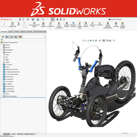
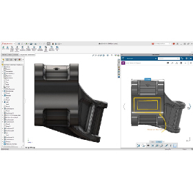
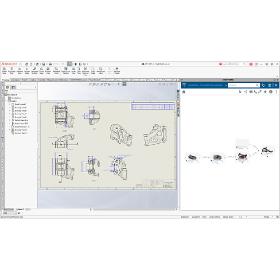
3D CAD system 'SolidWorks'

Solidworks is a 3D CAD software designed from the perspective of designers. It enables ideal design and modeling.

Solidworks analyzes the various features of each CAD based on customer requirements and proposes the optimal system.

  • solidworks_ipros_2.jpg
  • solidworks_ipros_3.jpg
  • Other CAD
  • 3D CAD
  • Other CAD related software
  • 3D CAD

Added to bookmarks

Bookmarks list

Bookmark has been removed

Bookmarks list

You can't add any more bookmarks

By registering as a member, you can increase the number of bookmarks you can save and organize them with labels.

Free membership registration

[BIM Software Implementation Case] Maren Corporation's Circulating Fluidized Bed Boiler

Improvement in detailed design of joints through modeling! A case where design errors were minimized.

We would like to introduce a case study on the implementation of BIM software in the design of Maren's Circulating Fluidized Bed (CFB) boiler. In this project, the use of "Tekla Structures" was essential for coordinating and adapting various piping and structural designs across different sections. Tasks were allocated early in the bidding phase, and effective detailed design of joints allowed for quick generation of drawings, minimizing design errors. At the points where structural steel components connect to the plant piping supports, structural members either converted IFC data to raw data of the same product or referenced IFC as information to be displayed in product drawings for verification. High-level detailed design has led to zero errors. *For more details, please refer to the PDF materials or feel free to contact us. (If the PDF button is not displayed) ⇩ The catalog can be downloaded from the special website below ⇩

  • 2D CAD Construction
  • 3D CAD
  • Other CAD related software
  • 3D CAD

Added to bookmarks

Bookmarks list

Bookmark has been removed

Bookmarks list

You can't add any more bookmarks

By registering as a member, you can increase the number of bookmarks you can save and organize them with labels.

Free membership registration

[BIM Software Implementation Case Study] Santiago International Airport

The production drawings are generated directly from the Tekla model! This ensures the management and improvement of production quality and safety.

VINCI Construction Grands Projets, in collaboration with Astaldi, is overseeing the conceptual design and construction of the expansion project at Santiago International Airport in Santiago, Chile. The conceptual design began in 2015, and the construction phase, which started in June 2016, had to be completed by the end of 2020. Since this project is designed based on strict seismic standards, adapting the structure to meet these requirements has been a significant challenge. To address this, collaboration tools such as "Tekla" and "Tekla BIMsight" were used. Thanks to the ability to create highly detailed models, adjustments can be made with certainty. *For more details, please refer to the PDF materials or feel free to contact us. (If the PDF button is not displayed) ⇩ The catalog can be downloaded from the special website below ⇩

  • 2D CAD Construction
  • 3D CAD

Added to bookmarks

Bookmarks list

Bookmark has been removed

Bookmarks list

You can't add any more bookmarks

By registering as a member, you can increase the number of bookmarks you can save and organize them with labels.

Free membership registration

[BIM Software Implementation Case] Blue Lock Quarry

Achieving great results even in challenging projects between remote locations through the use of Tekla Structure!

Fulton Hogan Quarries undertook a project to renovate the crushing and screening plant at the Blue Rock Quarry located in Cedar Creek, Queensland, Australia. The Blue Rock Quarry is situated approximately 50 km south of Brisbane's city center. The objective of this project was to expand the production capacity of the crushing and screening plant to meet the anticipated increase in demand for aggregate and road base products. Proindustrial Construction Company (Portugal) closely collaborated with contractors NascoTech and Southern Cross Engineering to carry out the civil works and structural design of the steel structures for this complex facility. The company was also responsible for creating various types of drawings and documents used in steel fabrication, including detailed designs for connections and joints, as well as shop drawings. Although this was a challenging project that required design collaboration between remote locations in Australia and Portugal, significant achievements were made thanks to the use of Tekla Structure and the dedicated efforts of the participating team members.

  • 3D CAD
  • 2D CAD Construction
  • antenna
  • 3D CAD

Added to bookmarks

Bookmarks list

Bookmark has been removed

Bookmarks list

You can't add any more bookmarks

By registering as a member, you can increase the number of bookmarks you can save and organize them with labels.

Free membership registration

3D CAD CADSUPERWorks Mini/Lite

A 3D CAD with intuitive operations that allows for smooth componentization.

【Features】 ■ Suitable for 3D printing applications ■ Equipped with interference check function between parts ■ Excellent compatibility with other CAD software ■ Capable of converting 3D information to 2D You can choose from two types: the "Mini model," which has the basic functions necessary for 3D modeling of parts, and the "Lite model," which includes assembly design functions. *For more details, please refer to the PDF catalog. If you would like detailed materials, please contact us at the information below. ■ Contact Marble Co., Ltd. Embedded Product Division, Product Business Department Phone: (03) 3419-6011

Added to bookmarks

Bookmarks list

Bookmark has been removed

Bookmarks list

You can't add any more bookmarks

By registering as a member, you can increase the number of bookmarks you can save and organize them with labels.

Free membership registration